Is the cooling fan life test related to humidity? -- Chungfo in-depth discussion of the influence of humidity on fan life

During the use of the cooling fan, the influence of humidity on the life of the fan cannot be ignored. Especially in industrial and household appliances, such as air conditioning cross-flow fans, cross-flow cooling fans and metal cross flow fans, humidity will not only affect the efficiency of heat dissipation, but also may adversely affect the internal structure of the fan.

How does humidity affect the life of the cooling fan?

High humidity environments pose multiple challenges to the motors, bearings and metal components inside cooling fans. High humidity may cause internal fan components to rust or corrode. In particular, fans with metal shells or internal components, such as metal cross flow fans, are more susceptible to humidity.


Chungfo's way of coping

In order to deal with the potential threat of humidity to the life of the fan, Chungfo strictly selects moisture-proof and rust-proof materials in the design and manufacturing process of the fan. For example, Chungfo's cross flow fan in air conditioners pay attention to corrosion resistance in the selection of materials, and have passed a number of humidity tests to ensure their long-term operation in high-humidity environments such as air conditioning equipment. Our cross-flow cooling fans are also designed with a moisture-proof seal structure, which effectively prevents moisture from entering the motor part, further extending the life of the fan.


Humidity has a profound impact on the life of cooling fans, especially for products such as metal cross-flow fans, cross flow cooling fans and air conditioning cross-flow fans that are exposed to high humidity for a long time. By selecting high-quality anticorrosive materials and conducting rigorous humidity life testing, Chungfo provides customers with more durable and reliable cooling fan products.

How to choose curved guides and linear guides

Curved guides and linear guides are two common types of guides. Both have support and guidance functions. Both can transfer the energy of movement to the receiving end to achieve stable movement. So what is the difference between the two?

From a structural point of view, linear guides are in the shape of a straight line, and they play a role in positioning, supporting and guiding in the movement of machinery and equipment. Curved guides are a special circular structure that is widely used in hardware, automation and precision mechanical equipment, and can maintain the axis position of relative movement unchanged.

From the perspective of motion trajectory, the movement mode of linear guides is linear motion driven by balls. The contact area between the balls and the guide grooves is small, so that the surface of the guide is evenly stressed and has a long life cycle. The arc guide realizes movement by the rolling of the balls on the curved surface of the guide. The curved surface of the guide bears a larger contact area, so the load capacity is higher than that of linear guides.  

From the application point of view, linear guides are widely used in CNC machine tools, semiconductor equipment, medical equipment and other fields due to their linear motion characteristics. They can provide high-precision, high-rigidity and low-friction motion control, and are suitable for high-speed and high-precision linear motion requirements.

Curved guides are more suitable for occasions that require curved motion or circular interpolation, such as robots, aerospace equipment, precision measuring instruments, etc. They can achieve smooth curved motion and precise circular interpolation, improving the motion performance and positioning accuracy of the equipment.

The above is the difference between linear guides and circular guides. When choosing guides, users in the machinery industry should choose the appropriate guide form according to the specific usage scenarios and needs to ensure the stability and reliability of the mechanical equipment.

Conversion Between Accelerated Aging of Xenon Lamp Aging Test Chamber And Outdoor Aging

Conversion Between Accelerated Aging of Xenon Lamp Aging Test Chamber And Outdoor Aging 

Generally speaking, it is difficult to have a detailed positioning and conversion formula for the conversion between accelerated aging of xenon lamp aging test chamber and outdoor aging. The biggest problem is the variability and complexity of the outdoor environment. The variables that determine the relationship between xenon lamp aging test chamber exposure and outdoor exposure include:

1. Geographical latitude of outdoor aging exposure sites (closer to the equator means more UV).

2. Altitude (Higher altitude means more UV).

3. Local geographical characteristics, such as the wind can dry the test sample or close to water will produce condensation.

4. Random changes in climate from year to year can lead to a 2:1 change in aging at the same location.

5. Seasonal changes (e.g., winter exposure may be 1/7 of summer exposure).

6. Direction of the sample (5° south vs. vertical facing north)

7. Sample insulation (outdoor samples with insulated backing age 50% faster than uninsulated samples).

8. Working cycle of xenon lamp aging box (light time and wet time).

9. The working temperature of the test chamber (the higher the temperature, the faster the aging).

10. Test the uniqueness of the sample.

11. Spectral Intensity Distribution (SPD) of laboratory light sources

xenon lamp aging test chamberObjectively speaking, accelerated aging and outdoor aging have no convertibility, one is a variable, one is a fixed value, the only thing to do is to obtain a relative value, rather than an absolute value. Of course, it is not to say that relative values have no effect; on the contrary, relative values can also be very effective. For example, you will find that a slight change in design may double the durability of standard materials. Or you may find the same looking material from multiple suppliers, some of which age quickly, most of which take a moderate amount of time to age, and a smaller amount that ages after longer exposure. Or you may find that less expensive designs have the same durability against standard materials that have satisfactory performance over actual service life, such as 5 years.

Drug Stability Test

Drug Stability Test

The effectiveness and safety of drugs have attracted much attention, and it is also a livelihood issue that the country and the government attach great importance to. The stability of drugs will affect the efficacy and safety. In order to ensure the quality of drugs and storage containers, stability tests should be performed to determine their effective time and storage state. Stability test mainly studies whether the quality of drugs is affected by environmental factors such as temperature, humidity and light, and whether it changes with time and the correlation between them, and studies the degradation curve of drugs, according to which the effective period is presumed to ensure the effectiveness and safety of drugs when used. This article collects the standard information and test methods required for various stability tests for customers' reference.

First, drug stability test criteria

Storage conditions of drugs:


Storage conditions (Note 2)

Long-term experiment

25℃±2℃ / 60%±5%RH or

30℃±2℃ /65%±5% RH

Accelerated test

40℃±2℃ / 75%±5%RH

Middle test (Note 1)

30℃±2℃ / 65%±5%RH

Note 1: If the long-term test condition has been set at 30℃±2℃/65% ±5%RH, there is no middle test; if the long-term storage condition is 25℃±2℃/ 60% ±5%RH, and there is a significant change in the accelerated test, then middle test should be added. And should be assessed against the criteria of "significant change".

Note 2: Sealed impervious containers such as glass ampoules can be exempted from humidity conditions. Unless otherwise determined, all tests shall be carried out in accordance with the stability test plan in the interim test.

The accelerated test data should be available for six months. The minimum duration of the stability test is 12 months for the middle test and the long-term test.


Store in refrigerator:


Storage conditions

Long-term experiment

5℃±3℃

Accelerated test

25℃±2℃ / 60%±5%RH


Stored in freezer:


Storage conditions

Long-term experiment

-20℃±5℃

Accelerated test

5℃±3℃

If the product containing water or solvents that may be subject to solvent loss is packaged in a semi-permeable container, the stability assessment should be conducted under low relative humidity for a long period of time, or an middle test of 12 months, and an accelerated test of 6 months, in order to prove that the drug placed in the semi-permeable container can withstand the low relative humidity environment.


Containing water or solvents


Storage conditions

Long-term experiment

25℃±2℃ / 40%±5%RH or 30℃±2℃ /35%±5% RH

Accelerated test

40℃±2℃;≤25%RH

Middle test (Note 1)

30℃±2℃ / 35%RH±5%RH

Note 1: If the long-term test condition is 30℃±2℃ / 35%±5%RH, there is no middle test.


The calculation of the relative water loss rate at a constant temperature of 40℃ is as follows:

Substituted relative humidity (A)

Control relative humidity (R)

Water loss rate ratio ([1-R]/[1-A])

60%RH

25%RH

1.9

60%RH

40%RH

1.5

65%RH

35%RH

1.9

75%RH

25%RH

3.0

Illustration: For aqueous drugs placed in semi-permeable containers, the water loss rate at 25%RH is three times that of 75%RH.


Second, Drug stability solutions

Common drug stability test criteria

(Source: Food and Drug Administration, Ministry of Health and Welfare)

Item

Storage conditions

Long-term experiment

25°C /60% RH

Accelerated test

40°C /75%RH

Middle test

30°C/65%RH


(1) Wide temperature range test

Item

Storage conditions

Long-term experiment

Low or sub-zero temperature conditions

Accelerated test

Room temperature and humidity or low temperature conditions


(2) Test equipment

1. Constant temperature and humidity test chamber

2. Drug stability test chamber

constant temperature & humidity test chamber

Electric Vehicle Component Reliability Test Solution

Electric Vehicle Component Reliability Test Solution

In the trend of global warming and gradual consumption of resources, automotive gasoline is also sharply reduced, electric vehicles are driven by electric energy, reducing the heat of internal combustion engine, carbon dioxide and exhaust gas emissions, for energy saving and carbon reduction and improve the greenhouse effect plays a huge role, electric vehicles are the future trend of road transportation; In recent years, the world's advanced countries actively develop electric vehicles, for thousands of components composed of complex products, its reliability is particularly important, a variety of harsh environments are testing the electronic system of electric vehicles [battery cell, battery system, battery module, electric vehicle motor, electric vehicle controller, battery module and charger...], Hongzhan Technology for you to sort out electric vehicle related parts reliability test solutions, hope to be able to provide customers with reference.

First, different environmental conditions will have different effects on parts and cause them to fail, so the parts of the car need to be tested according to the relevant specifications to meet international requirements and meet the foreign market, the following is the correlation between different environmental conditions and product failure:

A. High temperature will make the product aging, gasification, cracking, softening, melting, expansion and evaporation, resulting in poor insulation, mechanical failure, mechanical stress increase; Low temperature will make the product embrittlement, icing, shrinkage and solidification, mechanical strength reduction, resulting in poor insulation, cracking mechanical failure, sealing failure;

B. High relative humidity will make the product poor insulation, cracking mechanical failure, sealing failure and resulting in poor insulation; Low relative humidity will dehydrate, embrittlement, reduce mechanical strength and lead to cracking and mechanical failure;

C. Low air pressure will cause product expansion, electrical insulation deterioration of the air to produce corona and ozone, low cooling effect and lead to mechanical failure, sealing failure, overheating;

D. Corrosive air will cause product corrosion, electrolysis, surface degradation, increased conductivity, increased contact resistance, resulting in increased wear electrical failure, mechanical failure;

E. Rapid temperature changes will cause local overheating of the product, resulting in cracking deformation and mechanical failure;

F. Accelerated vibration damage or impact will cause the mechanical stress fatigue resonance of the product and lead to an increase in structural damage.

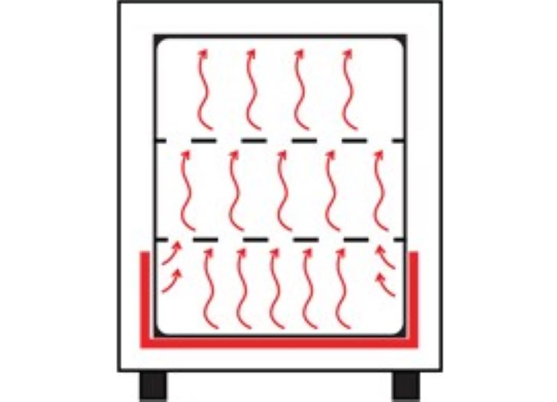
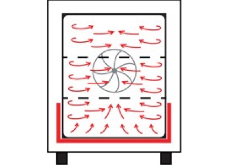
Therefore, products need to pass the following climatic tests to test the reliability of components: Dust (dust) test, high temperature test, temperature and humidity storage test, salt/dry/warm recovery test, temperature and humidity cycle test, immersion/seepage test, salt spray test, low temperature test, thermal shock test, hot air aging test, weather and light resistance test, gas corrosion test, fire resistance test, mud and water test, dew condensation test, high variable temperature cycle test, Rain (waterproof) test, etc.

The following are the test conditions for automotive electronics:

A. IC and interior lights for locomotives,

Recommended model: vibration of the comprehensive chamber

vibration of the comprehensive chamber

B. Instrument panel, motor controller, Bluetooth headset, tire pressure sensor, GPS satellite positioning system, instrument backlight, interior light, exterior light, automotive lithium battery, pressure sensor, motor and controller, automotive DVR, cable, synthetic resin

Recommended model: constant temperature and humidity test chamber

constant temperature and humidity test chamber

C. 8.4 "LCD screen for cars

Recommended model: thermal stress recombination machine

Second, automotive electronic parts are divided into three categories, including IC, discrete semiconductor, passive components three categories, in order to ensure that these automotive electronic components meet the highest standards of automotive safety. The Automotive Electronics Council(AEC) is a set of standards AEC-Q100 designed for active parts (microcontrollers and integrated circuits...)and AEC-Q200 designed for passive components, which specifies the product quality and reliability that must be achieved for passive parts. AEC-Q100 is the vehicle reliability test standard formulated by the AEC organization, which is an important entry for 3C and IC manufacturers into the international auto factory module, and also an important technology to improve the reliability quality of Taiwan IC. In addition, the international auto factory has passed the safety standard (ISO-26262). AEC-Q100 is the basic requirement to pass this standard.

1. List of automotive electronic parts for A.EC-Q100: Automotive disposable memory, Power Supply step-down regulator, Automotive photocoupler, three-axis accelerometer sensor, video jiema device, rectifier, ambient light sensor, non-volatile ferroelectric memory, power management IC, embedded flash memory, DC/DC regulator, Vehicle gauge network communication device, LCD driver IC, Single power Supply differential Amplifier, Capacitive proximity switch Off, high brightness LED driver, Asynchronous switcher, 600V IC, GPS IC, ADAS Driver Assistance System Chip, GNSS Receiver, GNSS front-end amplifier... 

B. Temperature and humidity test conditions: temperature cycle, power temperature cycle, high temperature storage life, high temperature working life, early life failure rate;

2. List of automotive electronic parts for A.AC-Q200: automotive grade electronic components (compliant with AEC-Q200), commercial electronic components, power transmission components, control components, comfort components, communication components, audio components.

B. Test conditions: high temperature storage, high temperature working life, temperature cycle, temperature shock, humidity resistance.

ESS Environmental Stress Screening Test Chamber

ESS Environmental Stress Screening Test Chamber

The full horizontal air supply system from right to left with large air volume is adopted, so that all specimen cars and specimens on the test are charged and divided, and the heat exchange is completed evenly and quickly.

◆ The utilization rate of test space is as high as 90%

◆ The special design of "uniform horizontal air flow system" of ESS equipment is the patent of Ring measurement.

Patent number: 6272767

◆ Equipped with air volume regulation system

◆ Unique turbine circulator (air volume can reach 3000~ 8000CFM)

◆ Floor type structure, convenient loading and unloading of tested products

◆ According to the special structure of the tested product, the box suitable for installation is used

◆ The control system and refrigeration system can be separated from the box, which is easy to plan or do noise reduction in the laboratory

◆ Adopt cold balance temperature control, more energy saving

◆ Equipment adopts the world's top brand Sporlan refrigeration valve with high reliability and long life

◆ The refrigeration system of the equipment adopts thickened copper pipe

◆ All the strong electric parts are made of high temperature resistant wires, which has higher safety

Heat Pipe Reliability Test

Heat Pipe Reliability Test

Heat pipe technology is a heat transfer element called "heat pipe" invented by G.M. rover of Los Alamos National Laboratory in 1963, which makes full use of the principle of heat conduction and the rapid heat transfer properties of the refrigeration medium, and transfers the heat of the heating object quickly to the heat source through the heat pipe. Its thermal conductivity exceeds that of any known metal. Heat pipe technology has been widely used in aerospace, military and other industries, since it has been introduced into the radiator manufacturing industry, making people change the design idea of the traditional radiator, and get rid of the single heat dissipation mode that simply relies on high air volume motor to obtain better heat dissipation effect. The use of heat pipe technology makes the radiator even if the use of low speed, low air volume motor, can also get satisfactory results, so that the noise problem plagued by air cooling heat has been well solved, opening up a new world in the heat dissipation industry.

Heat pipe reliability test conditions:

High temperature stress screening test: 150℃/24 hours

Temperature cycling test:

120℃(10min)←→-30℃(10min), Ramp: 0.5℃, 10cycles 125℃(60min)←→-40℃(60min), Ramp: 2.75℃, 10cycles

three-zone thermal shock test chamber

Thermal shock test:

120℃(2min)←→-30℃(2min), 250 cycles

125℃(5min)←→-40℃(5min), 250 cycles

100℃(5min)←→-50℃(5min), 2000 cycles(check once after 200 cycles)

two-zone thermal shock test chamber

High temperature and high humidity test:

85℃/85%R.H./1000 hours

high temperature and high humidity test chamber

Accelerated aging test:

110℃/85%RH/264h

high pressure accelerated aging tester

Other heat pipe test items:

Salt spray test, strength (blasting) test, leakage rate test, vibration test, random vibration test, mechanical shock test, helium combustion test, performance test, wind tunnel test

How Long Is the Xenon Lamp Weathering Test Chamber Equivalent to a Year of Outdoor Exposure?

How Long Is the Xenon Lamp Weathering Test Chamber Equivalent to a Year of Outdoor Exposure?

How long is the xenon lamp weathering test chamber equivalent to a year of outdoor exposure? How to test out its durability? This is a technical problem, but also a lot of users are concerned about the problem. Today's engineers of Lab Companion are going to explain this problem.

This problem looks very simple, in fact, it is a complex problem.We can not just get a simple number, let this number and the test time of the xenon lamp weathering test chamber to multiply, so as to get the outdoor exposure time, nor is the quality of our xenon lamp weathering test chamber not good enough! No matter how good the quality of the xenon lamp weathering test chamber is, how advanced it is, it is still impossible to find only a number to solve the problem. The most important thing is that the outdoor exposure environment is complex and changeable, affected by many factors, what are the specific?

1. The influence of geographical latitude

2. The influence of altitude

3. The influence of geographical environment when testing, such as wind speed.

4. The impact of the season, winter and summer will be different, summer exposure is 7 times the damage of winter exposure.

5. Direction of the test sample

6. Is the sample insulated or uninsulated? Samples placed on insulators will generally age much faster than those not placed on insulators.

7. Test cycle of xenon lamp weathering test chamber

8. Xenon lamp weathering test chamber operating temperature, the higher the temperature, the faster the aging

9. Testing of special materials

10. Spectrum distribution in the laboratory

xenon lamp weathering test chamber

Hydrogen Fuel Cell Environmental Simulation Test Scheme

Hydrogen Fuel Cell Environmental Simulation Test Scheme

At present, the economic development model based on the consumption of non-renewable energy based on coal, oil and natural gas has led to increasingly prominent environmental pollution and greenhouse effect. In order to achieve sustainable development of human beings, a harmonious relationship between man and nature has been established. The development of sustainable green energy has become a subject of great concern in the world.

As a clean energy that can store waste energy and promote the transformation from traditional fossil energy to green energy, hydrogen energy has an energy density (140MJ/kg) that is 3 times that of oil and 4.5 times that of coal, and is regarded as a subversive technological direction of the future energy revolution. Hydrogen fuel cell is the key carrier to realize the conversion of hydrogen energy into electric energy utilization. After the goal of carbon neutrality and carbon peak "double carbon" was proposed, it has gained new attention in basic research and industrial application.

Hydrogen fuel cell environmental test chamber of Lab Companion meets: fuel cell stack and module: 1W~8KW, fuel cell engine :30KW~150KW Low temperature cold start test: -40~0℃ Low temperature storage test: -40~0℃ High temperature storage test: 0~100℃.

Introduction of hydrogen fuel cell environmental test chamber

The product adopts functional modular design, explosion-proof and anti-static, and meets the relevant test standards. The product has the characteristics of high reliability and comprehensive safety warning, which is suitable for the test of the reactor and fuel cell engine system. Applicable power up to 150KW fuel cell system, low temperature test (storage, starting, performance), high temperature test (storage, starting, performance), wet heat test (high temperature and humidity


Safety parts:

1. Explosion-proof camera: real-time record the complete test situation in the box, easy to optimize or adjust in time.

2. Uv flame detector: high-speed, accurate and intelligent fire detector, accurate identification of flame signals.

3. Emergency air exhaust outlet: exhaust the toxic combustible gas in the box to ensure the safety of the test.

4. Gas detection and alarm system: intelligent and rapid identification of combustible gas, automatically generate alarm signals.

5. Double parallel single-pole screw mechanism cold unit: It has the characteristics of classification function, large power, small footprint and so on.

6. Gas precooling system: quickly control the gas temperature requirements to ensure cold start conditions.

7. Stack test rack: stainless steel stack test rack, equipped with water cooling auxiliary cooling system.


Fuel cell system test project

Fuel cell system test project

Fuel cell engine air tightness test

Power generation system quality

The volume of the battery stack

Insulation resistance detection

Starting characteristic test

Rated power starting test

Steady-state characteristic test

Rated power characteristic test

Peak power characteristic test

Dynamic response characteristic test

High temperature adaptability test

Fuel cell engine system performance test

Vibration resistance test

Low temperature adaptability test

Starting test (low temperature)

Power generation performance test

Shutdown test

Low temperature storage test

Low temperature start-up and operation procedures

/

/


Reactor and module test items

Reactor and module test items

Routine inspection

Gas leakage test

Normal operation test

Allow working pressure test

Pressure test of cooling system

Gas channeling test

Impact and vibration resistance tests

Electrical overload test

Dielectric strength test

Pressure difference test

Flammable gas concentration test

Overpressure test

Hydrogen leakage test

Freezing/thawing cycle test

High temperature storage test

Air tightness test

Fuel starvation test

Oxygen/oxidizer deficiency test

Short-circuit test

Lack of cooling/impaired cooling test

Penetration monitoring system test

Ground test

Starting test

Power generation performance test

Shutdown test

Low temperature storage test

Low temperature starting test


Product applicable standards:

GB/T 10592-2008 High and low temperature test chamber technical conditions

GB/T 10586-2006 Humidity test chamber technical conditions

GB/T31467.3-2015

GB/T31485-2015

GB/T2423.1-2208

GB/T2423.2-2008

GB/T2423.3-2006

GB/T2523.4-2008

Lab Ovens and Lab Furnaces

Lab Ovens and Lab Furnaces

Design with sample protection as the primary goal

Lab ovens are an indispensable utility for your daily workflow, from simple glassware drying to very complex temperature-controlled heating applications. Our portfolio of heating and drying ovens provides temperature stability and reproducibility for all your application needs. LABCOMPANION heating and drying ovens are designed with sample protection as a primary goal, contributing to superior efficiency, safety and ease of use.

Understand natural and mechanical convection

Principle of natural convection:

In a natural convection oven, hot air flows from bottom to bottom, so that the temperature is evenly distributed (see figure above). No fan actively blows the air inside the box. The advantage of this technology is ultra-low air turbulence, which allows for mild drying and heating.

Principle of mechanical convection:

In a mechanical convection (forced air drive) oven, an integrated fan actively drives the air inside the oven to achieve uniform temperature distribution throughout the chamber (see figure above). A major advantage is excellent temperature uniformity, which enables reproducible results in applications such as material testing, as well as for drying solutions with very demanding temperature requirements. Another advantage is that the drying rate is much faster than natural convection. After opening the door, the temperature in the mechanical convection oven will be restored to the set temperature level more quickly.