Hydrocracking Bubbling Bed Technology A Key Solution for Heavy Oil Processing and Sustainable Energy Development

Hydrocracking bubbling bed technology is an advanced petroleum refining process specifically designed for the deep processing of heavy oil and solid-containing petroleum products. As global conventional crude oil resources gradually deplete, and the trend toward heavier crude oil becomes increasingly evident, hydrocracking bubbling bed technology is playing an increasingly critical role in the energy industry. This technology addresses the dual challenge of global energy shortages and the need for improved energy efficiency, particularly in the context of rapid economic growth in developing countries and the resulting surge in energy demand. Below is a detailed explanation of the hydrocracking bubbling bed process, its key equipment, and industrial applications.
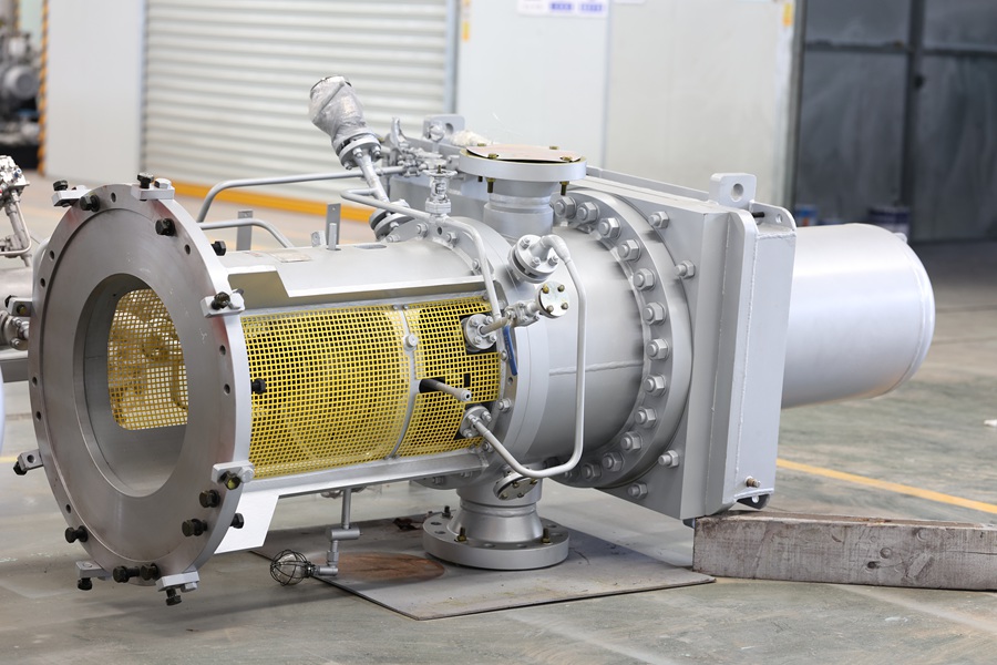
Hydrogenation Ebullating PumpHydrogenation Ebullating Pump

1. Working Principle of Hydrocracking Bubbling Bed Technology

Hydrocracking bubbling bed technology is based on hydrocracking reactions aimed at breaking down large molecular organic compounds in heavy oil and solid-containing petroleum products into smaller, lighter hydrocarbons through the combined action of catalysts and hydrogen. This process improves oil quality, reduces sulfur, nitrogen, and oxygen impurities, and enhances the fluidity and combustion properties of the final product. The core of hydrocracking lies in using hydrogen under high-temperature and high-pressure conditions to cleave large molecules into smaller ones, ultimately yielding high-quality light oil products.

In a bubbling bed reactor, hydrogen is injected at the bottom, mixing with the heavy oil and catalyst to form a fluidized, bubbling state. Due to the extended contact time between the catalyst and the feedstock in this gas-liquid-solid three-phase system, efficient hydrocracking reactions can occur. This technology is especially effective in processing high-sulfur, high-nitrogen, and other impurity-laden feedstocks while significantly improving yield and economic performance.

2. Role of Circulation Pumps (Ebullating Pumps)

Circulation pumps, also known as ebullating pumps, are essential components of the hydrocracking bubbling bed system. Their primary function is to ensure the continuous circulation of feedstock and catalyst within the reactor, maintaining uniform temperature distribution and a stable reaction environment. By circulating the feedstock, the pump ensures thorough contact between the oil and catalyst, thus improving reaction efficiency and preventing localized overheating or catalyst deactivation.

Additionally, circulation pumps help control the reactor's pressure and flow, ensuring the continuous flow of the oil feed. Given the harsh operating conditions in hydrocracking (high temperatures, high pressures, and the presence of solid particles), these pumps must be designed with high resistance to wear, corrosion, and thermal stress. They must also withstand prolonged exposure to extreme conditions while ensuring system stability and efficiency.

3. Process Advantages and Application Fields

Compared to traditional catalytic cracking processes, hydrocracking bubbling bed technology offers several notable advantages:

  • Wide Range of Feedstocks: This technology can process a variety of low-quality feedstocks such as heavy oil, residual oil, kerosene, and solid-containing petroleum products, offering strong adaptability.
  • High Product Yield: The hydrocracking process efficiently breaks down heavy molecules, increasing the yield of light oil products and resulting in higher overall output than conventional methods.
  • Environmental Benefits: The hydrocracking process effectively removes harmful impurities such as sulfur and nitrogen, reducing the pollutant content in the final product and meeting stricter environmental regulations.
  • Improved Energy Efficiency: By converting heavy components into more combustible light oil products, hydrocracking significantly enhances energy utilization efficiency.


The application conditions of hydrogenation boiling pumps are complex, the medium temperature is as high as 500℃, the inlet pressure is 30MPa, and the medium is highly corrosive. At present, the technology of this product is only mastered by a few countries, and there are very few factories that can produce it, and it is expensive. Fortunately, Huasheng is one of the very few factories that can produce this pump.

In 2018, Huasheng Pumps and Valves undertook the "Residue Oil Hydrogenation Boiling Pump Research and Development" project, a major equipment localization project of Sinopec Headquarters. The company relies on the operating parameters of Sinopec's 2 million tons/year liquid diesel hydrogenation unit for research and development. Its rated flow rate: 835m³/h, head: 79m, temperature: 410℃, wet motor power: 250kw. It took 4 years, and the product was delivered in 2022 and is currently running well. The success of the project has enabled China to break the foreign monopoly on hydrogenation boiling pump technology and reduce costs.
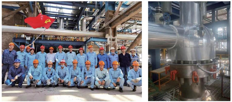
Hydrogenation Ebullating Pump projectHydrogenation Ebullating Pump project

As global energy structures shift and environmental requirements tighten, hydrocracking bubbling bed technology presents significant growth potential. Key future development trends include:

  • More Efficient Catalysts: Research and development of more efficient, longer-lasting catalysts will further improve reaction efficiency and product yield.
  • Intelligent Control Systems: The application of advanced automation and data analysis technologies will optimize the reaction process, reduce energy consumption, and enhance system stability.
  • Expanded Application Range: With ongoing technological advancements, hydrocracking bubbling bed technology is expected to extend into other unconventional resource processing areas, such as coal-to-liquids and oil sands extraction.

The development and application of hydrocracking bubbling bed technology provide an effective solution for the utilization of heavy oil and solid-containing petroleum products. This technology offers a viable path for addressing the depletion of conventional oil resources while meeting the growing demand for energy. Circulation pumps, as a critical component of the process, play a pivotal role in ensuring the success of the entire operation. Looking ahead, as the technology continues to evolve, hydrocracking bubbling bed technology will remain a key player in global energy production and refining, contributing to the sustainable development of the energy sector.


 

Applicable standards of the washing color fastness tester

The double-tub washing color fastness tester is used for washing color fastness, dry cleaning color fastness, rinsing color fastness, detergent efficiency and other washing and dry cleaning color fastness tests of various textiles, and evaluates the washing color fastness performance of textiles.

Main parameters:

1. Test container position: (12+12)×2.

2. Rotation speed: 40±2rpm.

3. Washing cup: 500ml and 1200ml, each tank contains 24 cup slots (12 large and 12 small), to meet different test requirements

4. Temperature control can reach 98℃.

Applicable standards:

ISO105M&SC4A, 5, 37, P3BIWSTM7, 115, 177, 193, 240, 241, AATCC2, 3, 28, 61, 62, 86, 132, 151, 190,BS1006NEXT2, 3, 5

C4A Color fastness to washing detergents

C5 Color fastness to dry cleaning

C10A Color fastness to oxidative bleaching damage

C22 Color fastness to residual staining in toilets

C23 Color fastness to toilet solvents

C37 Color fastness to chlorinated water and swimwear

P38 "MST" washing stability

BS EN ISO 105C01-C05 Color fastness to washing

BS EN ISO 105C06 Color fastness to household and commercial laundry

BS EN ISO 105C08 Color fastness to phosphate-free household and commercial laundry

BS EN ISO 105C09 Color fastness to household and commercial laundry - Oxidative bleaching using low temperature bleach activators

BS EN ISO 105D01 Color fastness to 1,000 washes

BS EN ISO 105E03 Color fastness to chlorinated water

BS EN ISO 105X05 Color fastness to organic solutions


Fabric folding thickness and shrinkage detection method

1. Folding thickness of fabric Fabrics are divided into thicknesses, and clothing made from fabrics also has thicknesses; this thickness is expressed by the folding amount, so the folding amount needs to be considered when making patterns. The folding amount indicates the degree of folding thickness of the fabric, which is present in any garment. The folding amount is just different in size. The thicker the fabric, the greater the folding amount; the thinner the fabric, the smaller the folding amount. Example: The folding amount of denim jeans W: 1.2cm K: 0.6cm H: 1.2cm SB: 0.6

2. Shrinkage of fabrics

There are two types of clothing fabrics: natural fabrics and chemical synthetic fabrics

a: Natural fabrics: woven from natural fibers, mainly plants, such as cotton and linen, which have a large shrinkage rate, and animals, such as silk, wool, and leather, which have a small shrinkage rate.

b: Chemical synthetic fabrics: The main ones woven from chemical synthetic fibers include polyester, nylon, acrylic, chlorine fiber, chlorine fiber, etc., which do not shrink.

(The other kind of fabric is a mixture of natural and chemical materials, such as polyester and cotton, with low shrinkage)

Due to the characteristics of natural fabrics, natural fabrics shrink after washing. Cotton and linen fabrics shrink the most. In daily life, especially casual clothing, most pure cotton fabrics are used, so the shrinkage rate must be considered when producing paper patterns. .

No shrinkage: the size of a before washing is m and the size after washing is n, then a=m-n/m×100%

Since the fabric has two yarn directions: transverse and longitudinal, there are also two shrinkage rates:

a vertical = m vertical - n vertical / m vertical × 100%

a horizontal = m horizontal - n horizontal / m horizontal × 100%

Generally speaking, when making a paper pattern, the shrinkage rate of the fabric will be informed. If we don't know the shrinkage rate of this fabric, we can use the following two methods to calculate the shrinkage rate.

a: Don't consider the shrinkage rate first, directly make a paper pattern of the middle code to make a board, and then take it to the washing plant to wash (note that the washing method must be the same as the washing method of the bulk goods). After washing, measure the board again, compare it with the finished product specifications, subtract more, and add less. This way, the board is more accurate, but it takes too long to make the board.

b: Take a piece of fabric for bulk goods, sew the edges around, and use a pen to draw a square in the middle of the cloth with a side length of 40cm, two sides parallel to the fabric grain, and two sides perpendicular to the fabric grain 40x40cm, then wash it. The washing method is the same as the bulk goods. After washing, measure each side of the square, and it becomes 36x36cm data.

Reuse a=m-n/m×100%

a vertical 40-38/40x100%=8%

a horizontal=40-36/40x100%=10%

Therefore, the shrinkage rate of the fabric is: vertical: 5% horizontal: 10%.

However, considering the fixing effect of the seams, the shrinkage rate of clothing is actually slightly smaller, so it should be determined according to the specific situation.

The purpose of calculating a longitudinal and a transverse is to calculate the length with a longitudinal and the circumference with a transverse to calculate the shrinkage rate in order to calculate the data K before washing. From the shrinkage rate formula, it can be deduced that K=?

Furthermore, it can be deduced that: K longitudinal=e longitudinal/1-a longitudinal (to calculate the length of clothing)

K transverse=e transverse/1-a transverse (to calculate the circumference of clothing)

For the parts where the vertical and horizontal are connected, the shrinkage rate is taken as the average value, such as the fabric patterns of the waist and the waistband are perpendicular to each other.

Example: w: 66cm-68.6cm (shrinkage rate: vertical 3%/horizontal 4%) SL: 55.9-57.5cm.

Email: hello@utstesters.com

Direct: + 86 152 6060 5085

Tel: +86-596-7686689

Web: www.utstesters.com

Maintenance method of universal strength tester

1. Each time you turn on the instrument and start a new set of tests, you must press the reset button to restart the instrument, otherwise the data processing will be incorrect.

2. When the instrument is reset and the zero key is pressed, it contains the function of automatically clearing (peeling) the force sensor. Please note that when starting the instrument, the upper clamp should not be subjected to any additional force except its own weight, otherwise, inaccurate peeling will lead to inaccurate testing.

3. The instrument input setting parameters should be performed before a set of tests begins, otherwise, data processing errors will occur.

4. The instrument has been calibrated for the strong force indication before leaving the factory. Non-professional calibration and maintenance personnel are not allowed to calibrate it arbitrarily, otherwise the instrument will cause inaccurate force measurement.

5. The force sensor can be cleared while waiting for the test and calibrating the display status. After pressing the zero key, wait 2 seconds before starting the test.

6. In the instrument automatic control program, there is a test value judgment program, which will automatically delete the obviously wrong test data (including the measured value after the sensor zero point drifts seriously and the impact strength value); please note that if the instrument automatically deletes the current test value for many times in a row, it is generally because the reset value has been offset. You should press the reset key to reset it again before continuing the test.

7. The maximum allowable setting of the sample value and the number of sample varieties of this machine are limited to 255 times. At the same time, the number of samples × the number of samples <500, the computer automatically determines whether it is a memory overflow and prompts with text on the LCD screen.

8. If you want to print the test curve, you should print it after the current test is completed, that is, only print the current test curve. If this test is the last test of this group, print the curve first and then print the report.

9. Note that the force on the upper clamp should be less than the full scale value of the instrument. Avoid the impact of the upper clamp, otherwise it is easy to damage the force sensor.

10. Clean and maintain the instrument well, and lubricate the screw and guide rod in time.

11. Regularly calibrate the instrument to ensure the accuracy of the instrument's measurement value.

12. Non-professional maintenance and calibration personnel are not allowed to dismantle the instrument. The measurement performance must be calibrated after each dismantling to avoid instrument inaccuracy.

13. If there is a sudden failure during operation, emergency stop must be performed and restart must be performed.


Email: hello@utstesters.com

Direct: + 86 152 6060 5085

Tel: +86-596-7686689

Web: www.utstesters.com


Operation method of electronic fabric strength machine

Take the fabric stretching function as an example:

1. Operation adjustment

(1) Clamping distance adjustment

Before the instrument tensile test, the clamping distance between the upper and lower clamps must be adjusted to be consistent with the set value. The specific adjustment method is:

①. Press the up button on the control panel to make the crane rise. After rising a certain distance, press the stop button to stop the crane.

②. According to the required length of the sample, move the lower limit block to the position of the corresponding hole (or indicator arrow) on the limit rod and tighten it. The limit rod is drilled with a lower limit positioning stop hole for positioning the lower limit collision block. Each hole indicates the clamping distance of the clamp to be tested.

③. Press the down button to make the crane descend to the lower limit position and stop automatically. Use a steel ruler to measure the distance between the upper and lower clamps. If there is a slight difference with the clamping distance requirement, the height of the upper limit collision nut can be adjusted (thread adjustment) to finally make the distance between the upper and lower clamps consistent with the clamping distance requirement.

④. According to the adjusted distance between the upper and lower clamps, check whether it is consistent with the set clamping distance. If not, repeat the above steps until it meets the requirements.

(2) Selection of pre-tension clamps

According to the specifications of the specimen, calculate the pre-tension value required for clamping the specimen according to the test standard, and then select the corresponding pre-tension clamp. (3) Test parameter setting According to the standard requirements, enter the value as prompted by the LCD screen. (4) Adjustment of stretching speed When testing a specimen, prepare a number of additional specimens more than the specified number of test strips for preliminary testing to determine the stretching speed.

(3) Test parameter setting

According to the standard requirements, enter the value as prompted by the LCD screen.

(4) Adjustment of stretching speed

When testing a specimen, prepare a number of additional specimens more than the specified number of test strips for preliminary testing to determine the stretching speed.

2. Clamping the specimen specimen clamp

According to the customized function configuration, take the corrugated clamp for fabric stretching function as an example:

a. Rotate the clamp handle to loosen the corrugated clamp;

b. Insert one end of the test strip from the bottom of the upper clamp into the opened upper clamp clamping mouth, and keep the specimen and the jaws straight:

c. Rotate the handle to clamp it;

d. Loosen the lower clamp handle to open the lower clamp jaws;

e. Pass the other end of the test strip clamped in the upper clamp through the lower clamp jaws, and clamp the strip through the jaws with the selected pre-tension clamp so that the specimen is straightened under the action of the pre-tension clamp;

f. Rotate the lower clamp handle to clamp the lower end of the specimen, and then remove the pre-tension clamp, and the specimen clamping is completed.

3. Tensile test

Press the start button on the base, the crane rises, and stretches the sample clamped between the upper and lower clamps. After breaking, the crane automatically returns to its original position, and the instrument automatically records and displays the maximum strength value (peak strength value), tensile length, elongation, breaking time and test number at the time of breaking.

4. Check and process the test results

①. Check the fracture position of the sample. If the distance between the fracture and the upper and lower clamp jaws is s5mm, cancel the test value and re-test. Press the delete key, and the instrument will process the test value accordingly (minus one, the test is invalid).

②. If the fracture position of the sample is normal; the test is valid, the strength and elongation curve of the test can be printed at this time, and then check the test number value. If the sample display value (the number of tests for this type of sample) is consistent with the set value, it indicates that the test of this type of sample is completed. Replace the new sample and continue the test; if the display value is less than the set sample value, repeat the previous action and continue the test on the strip sample of this type of sample.

5. Printing test report

After the sample has been tested for the required number of times, that is, when the sample display value is consistent with the set sample value, it means that the test of this sample has been completed and it can be printed at this time. When printing, press the print key, select the print format, and then print the test report after confirmation. Before printing, ensure that printing paper should be added to the printer; in addition, the printer's online indicator (ONLINE) must be on. After printing, you can continue to test, and press the print key later to print. If you need to perform a new test after printing, you need to press the reset key and then test again. If you need to print repeatedly, press the print key again after printing.

6. Display the test results directly through the LCD screen on the display panel.

7. After one set of samples is tested, press the reset button to restart the instrument and clear the existing stored data in the computer so that it can start working again.


Email: hello@utstesters.com

Direct: + 86 152 6060 5085

Tel: +86-596-7686689

Web: www.utstesters.com


Shoe material testing equipment

There are many types of shoe material testing equipment, which are used to test various properties of shoe materials. The following are some common shoe material testing equipment:

Toe bending test machine: used to test the bending resistance of finished shoes and evaluate the bending resistance of shoe materials.

Upper leather stretch test machine: simulates the compression, stretching and bending of the upper during walking after wearing shoes.

Leather wear test machine: suitable for the wear resistance test of wear-resistant materials used on the heels of leather shoes.

Bending test machine: used to connect and bend test pieces of a certain size, and observe the degree of cracking and damage of the test pieces after a certain number of bends.

Leather shoe shank stiffness tester: suitable for the determination of the longitudinal bending stiffness of the leather shoe shank.

Safety shoe compression tester: suitable for steel toe compression and steel mid-plate puncture resistance test of all types of safety shoes.

Anti-puncture bending test machine: test the bending resistance of safety insoles.

Leather Flex Tester: Determines the material's resistance to cracking or flexing at a bend crease.

Rubber resilience impact tester: measures the impact resistance of elastic materials and soft porous materials.

Sole static anti-slip tester: tests the static anti-slip properties of outsoles, high-heeled shoe heels and related outsole materials.

Testing machine double-arm tensile machine: used for various materials for tensile, compression, bending, shearing, bonding strength, peeling, tearing and other tests, suitable for a variety of materials.

Low-temperature sole bending tester: examines the bending resistance of the sole under low temperature environment.

Whole shoe wear tester: suitable for testing the wear resistance of finished shoe soles and molded soles (sheets).

Heel impact tester: simulates the ability of women's high-heeled shoes to resist sudden impact when wearing and walking.

Safety shoe withstand voltage tester: tests the voltage value that the sole or insulating shoe material can withstand.

Water vapor permeability tester: measures the water vapor permeability of leather or synthetic materials used for shoes or personal protective equipment.

Anti-yellowing chamber detector: simulates sunlight to measure anti-yellowing performance.

Rubber soles and shoes ozone aging tester: Evaluate the weather resistance of rubber soles and shoes in ozone environment.

These equipments cover a variety of performance tests such as bending resistance, wear resistance, impact resistance, puncture resistance, voltage resistance, water vapor permeability, etc. of shoes, and are indispensable tools in shoe production and quality control.


Email: hello@utstesters.com

Direct: + 86 152 6060 5085

Tel: +86-596-7686689

Web: www.utstesters.com

What are the factors that affect textile shrinkage?

Measuring shrinkage is one of the common testing methods for textile testing, but practice has proven that the shrinkage of textiles is affected by many factors. Therefore, understanding the factors that affect textile shrinkage has positive significance for the scientificity and accuracy of measuring shrinkage.


Common factors that affect textile shrinkage include:

1.Fiber composition: Compared with synthetic fibers (such as polyester, acrylic), natural plant fibers (such as cotton, linen) and plant regenerated fibers (such as viscose) are prone to moisture absorption and expansion, so the shrinkage rate is larger, while wool is due to the scale structure on the fiber surface. It is easy to felt, which affects its dimensional stability.


2.Production and processing process: Since the fabric will inevitably be stretched by the machine during the dyeing, printing, and finishing processes, tension exists on the fabric. However, the fabric can easily release the tension when exposed to water, so we will Noticed fabric shrinkage after washing. In actual processes, we generally use pre-shrinking to solve this problem.


3.Fabric structure: Generally speaking, the dimensional stability of woven fabrics is better than that of knitted fabrics; the dimensional stability of high-density fabrics is better than that of low-density fabrics. Among woven fabrics, the shrinkage rate of plain weave fabrics is generally smaller than that of flannel fabrics; while among knitted fabrics, the shrinkage rate of plain knitted fabrics is smaller than that of ribbed fabrics.


4. Washing and care process: Laundry care includes washing, drying, and ironing. Each of these three steps will affect the shrinkage of the fabric. For example, the dimensional stability of hand-washed samples is better than that of machine-washed samples, and the washing temperature will also affect its dimensional stability. Generally speaking, the higher the drying oven temperature, the worse the stability. The drying method of the sample also has a relatively large impact on the shrinkage of the fabric.


Email: hello@utstesters.com

Direct: + 86 152 6060 5085

Tel: +86-596-7686689

Web: www.utstesters.com


Middle Eastern Client Visit and Aluminum Extrusion Press Recommendation

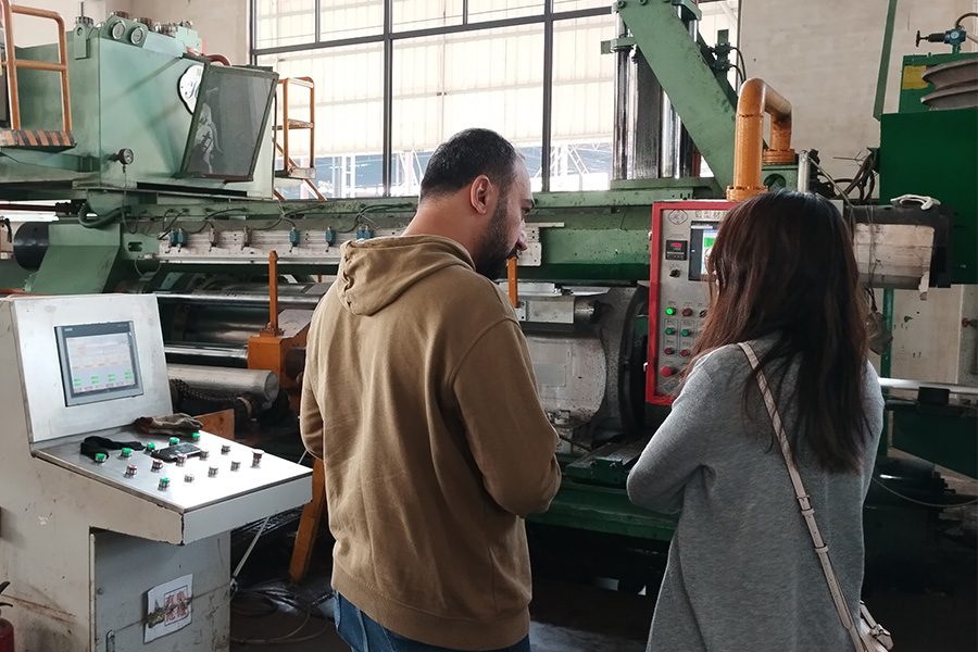
Recently, a client from the Middle East visited our factory and intended to purchase an aluminum extrusion press for manufacturing door and window materials.

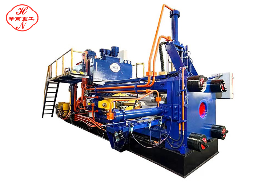
Aluminum Extrusion MachineAluminum Extrusion Machine

We recommended the customer to purchase a 5-inch extrusion press, specifically our 1100T aluminum extrusion press. Through our discussion, we realized that the customer had limited knowledge about extrusion presses. Previously, he used to purchase aluminum materials for making doors and windows, but now he plans to buy an extrusion press to produce aluminum materials himself.

Someone had suggested that he should buy an 1800T aluminum extrusion press for producing door and window aluminum materials. However, based on the sizes of the door and window materials he needs, we recommended the 1100T aluminum extrusion press instead.


Our Huanan 1100T aluminum extrusion press is also a 5-inch aluminum extrusion press, which is suitable for extruding various door and window aluminum profiles. The extrusion cylinder specifications of our 1100T aluminum extrusion press machine are:

Diameter: 132mm

Length: 800mm

Applicable aluminum billet size:

Diameter: 127mm

Length range: 400–750mm


Considerations When Extruding Aluminum: Extrusion Pressure


extrusion press machineextrusion press machine


When extruding aluminum, it is crucial to consider the extrusion pressure. If the extrusion press tonnage is too high relative to the aluminum billet diameter and alloy type, the following issues may occur:

1. Over-Extrusion

Excessive Metal Flow Rate: Too much pressure can cause excessively fast metal flow, affecting dimensional accuracy and surface quality.

Overheating: Excessive extrusion pressure can lead to rapid temperature rise, potentially causing surface roughness, cracks, or even burning.


2. Mold and Die Damage

Shortened Die Lifespan: Excessive pressure may exceed the die’s load capacity, leading to rapid wear or even breakage.

Die Deformation: Continuous use of an overpowered press can cause plastic deformation of the die, affecting profile accuracy.


3. Equipment Damage

Accelerated Extrusion Cylinder Wear: Higher pressure accelerates wear on the inner wall of the extrusion cylinder, shortening its lifespan.

Hydraulic System Overload: If the tonnage is too high, the hydraulic system may overheat, experience pressure failures, or even develop leaks.


4. Negative Impact on Product Quality

Coarse Grain Structure: Excessive extrusion speed can lead to larger metal grains, reducing mechanical performance.

Increased Defects: High stress and temperature may introduce bubbles or inclusions inside the aluminum, affecting product quality.

Reduced Dimensional Accuracy: Overpowering the extrusion process may lead to unstable profile dimensions and out-of-tolerance products.


5. Increased Production Costs

Higher Energy Consumption: A high-tonnage extrusion press consumes more energy, leading to unnecessary waste if the press is oversized.

Increased Maintenance Costs: Faster wear and tear on molds, extrusion cylinders, and hydraulic systems lead to higher maintenance and replacement costs.


Choosing the Right Extrusion Press


1100T aluminum extrusion press1100T aluminum extrusion press


When purchasing an aluminum extruder, it is essential to determine the size of the aluminum profiles to be produced and ensure that the press tonnage is appropriate.

For those who are new to the industry and considering purchasing an extrusion press, you can contact our sales team at Huanan Heavy Industry via WhatsApp or Email. Our sales team is highly knowledgeable about extrusion presses and can consult with engineers to provide professional guidance.

WhatsApp: +86 13450865812Email: jessica@huananmachine.com

aluminum extruderaluminum extruder

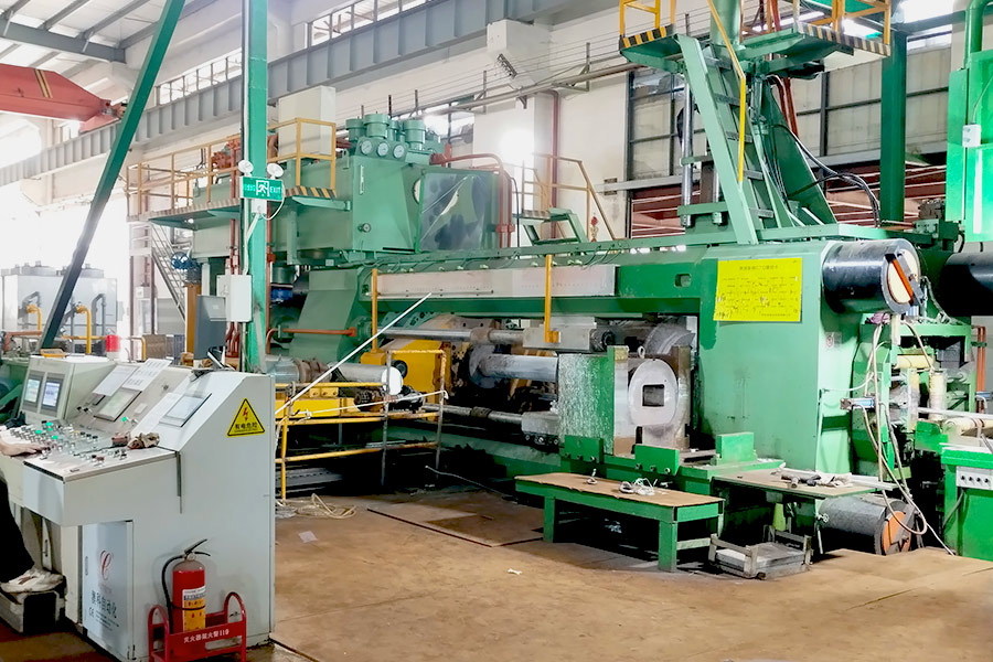
Finally, we took our Middle Eastern client to the production line to observe the entire mechanical production process and inspect the 5-inch aluminum extrusion machine in action. This helped the customer better understand the Aluminum extrusion process and the necessary machinery, giving him a clearer view of the entire aluminum manufacturing process.


The similarities and differences between copper extrusion and aluminum extrusion

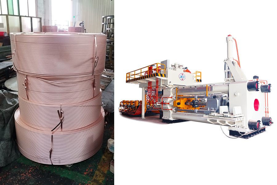
                   aluminum and copper extrusion processesaluminum and copper extrusion processes 

             The similarities and differences between copper extrusion and aluminum extrusion

Aluminum is one of the most common materials in our daily lives and an essential metal in various industries. However, in addition to aluminum, copper is also a widely used metal due to its excellent electrical and thermal conductivity, corrosion resistance, and other favorable properties. Copper has broad applications across multiple industries, such as:


Electrical and Electronics: Wires, cables, transformers, motors, and electronic components.

Construction: Piping systems, electrical wiring, and copper conductors.

Automotive: Electrical systems, radiators.

Industrial Equipment: Heat exchangers, valves, pumps, bearings, and gears.

Telecommunications: Cables.

Energy: Solar panels, generators.

Healthcare: Medical devices, surgical instruments, door handles, and handrails due to its antibacterial properties.

Both aluminum and copper are produced through extrusion processes, where pressure is applied to metal billets, forcing them through molds to form the desired shapes. While the basic production process is similar for both materials, copper and aluminum differ significantly in their properties, which affects their production methods and equipment.


Production Process:

Both aluminum and copper extrusion processes involve applying hydraulic or mechanical pressure to metal billets, which are heated to increase their plasticity for easier extrusion. The extrusion equipment, including extrusion cylinders, molds, extrusion rods, and heating systems, are similar for both metals. However, because copper and aluminum have different properties, the specific production conditions, such as temperature and pressure, vary.


Differences Between Aluminum and Copper:


Aluminum:

Density: Low

Melting Point: Approximately 660°C

Plasticity: High, making it easier to extrude

Extrusion Pressure: Relatively low


Copper:

Density: High

Melting Point: Approximately 1085°C

Hardness: Higher, making extrusion more difficult

Extrusion Pressure: Higher due to its hardness

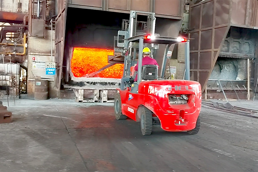
Because of these differences, the heating temperature required for aluminum and copper extrusion is not the same. For aluminum, the heating temperature typically ranges from 400°C to 500°C, while for copper, it is generally higher due to its higher melting point. This difference in properties also results in copper requiring higher extrusion pressures compared to aluminum. This is one of the reasons why our HuaNan heavy Industry can produce copper extruders in addition to aluminum extruders.


Molds:

Mold material plays a crucial role in determining the extrusion quality. Aluminum extrusion molds are usually made from high-strength steel, offering durability. Copper extrusion molds, on the other hand, require materials with higher wear and heat resistance, making them less durable than aluminum molds.


Lubrication:

The choice of lubricant also differs. Aluminum extrusion typically uses graphite or oil-based lubricants, while copper extrusion requires high-temperature lubricants such as glass lubricants to manage the higher extrusion pressures.


Cooling:

After extrusion, cooling methods vary. Aluminum cools faster and is typically cooled using air or water, while copper requires a slower, gentler cooling process to prevent cracking.


Post-Treatment:

Aluminum often undergoes anodizing or spraying treatments, while copper is usually treated through electroplating or polishing to achieve a smooth finish.


Production Costs:

Despite similar production processes, the costs of extruding copper are generally higher than for aluminum due to copper's higher extrusion pressures and material costs.


Summary:

In conclusion, while the extrusion processes for aluminum and copper are fundamentally similar, the differences in their material properties lead to distinct requirements for heating, extrusion pressure, mold materials, lubrication, cooling, post-treatment, and cost. Copper extrusion typically involves higher pressures, more specialized molds, and more complex handling, which results in higher production costs compared to aluminum extrusion.

Why We Are Confident in Our Aluminum Extrusion Machines

                                  Aluminum Extrusion MachineAluminum Extrusion Machine                         


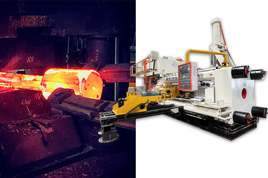
Forging and casting are two common metalworking processes, each with its own advantages and disadvantages, suitable for different applications.


Let’s start by looking at the benefits of forging over casting:


Higher Strength: During the forging process, the grain structure of the steel is compressed and refined, enhancing its strength and toughness.


Better Fatigue Performance: Forged parts can withstand repeated stresses, making them ideal for high-load and dynamic stress applications.


Fewer Internal Defects: Forging reduces defects such as porosity and shrinkage, improving the material’s density and overall quality.


High Dimensional Precision: Forged parts have precise dimensions, requiring minimal post-processing, which saves both material and time.


At Huannan Heavy Industry, we use forging for the main components of our aluminum extrusion machines, including the front beams, tension columns, extrusion rods, and extruder container. This allows our machines to better withstand the impact forces during extrusion.


In contrast, many competitors use cast steel for components like the front beam and tension column. The drawback of casting is that the material’s strength is lower due to a coarser grain structure, and casting is more prone to internal defects like porosity and shrinkage. These defects can weaken the material and affect its overall performance.


Aluminum extrusion machines made with cast steel are more likely to suffer from insufficient toughness and strength, making them prone to damage under prolonged operational pressure. While casting is more cost-effective, the quality simply cannot match that of forged steel. This is why our extrusion machines may be priced higher than those of our competitors, but the superior quality and longer service life make them a much better investment in the long run.


This is the confidence we have in Huannan Heavy Industry’s aluminum extrusion machines—our commitment to quality sets us apart.